
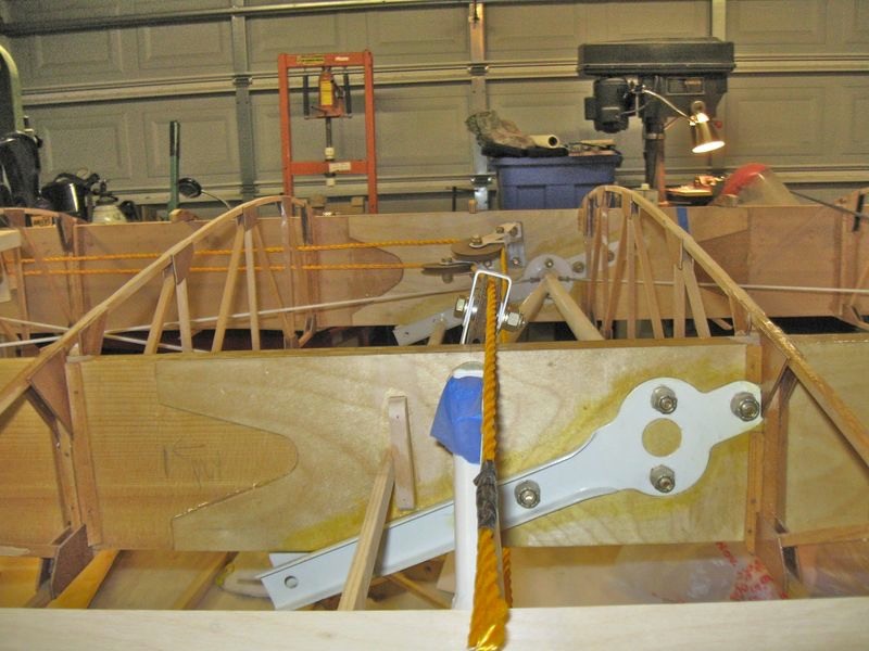
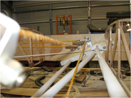
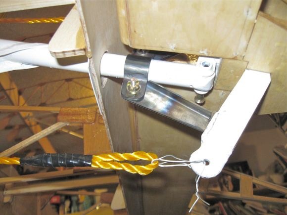
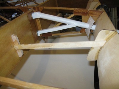
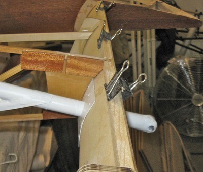
The next step was running the aileron cables and pulleys. There was not much information in the plans as to the location of the pulleys on the front spar; only limited drawings of the rear spar pulley. Gathering info for the pulleys proved to be very frustrating. I tried many locations and gathered pictures from other builders before finally coming up with this set up. I used 3/16″ poly rope to simulate the 1/4″ cable that will be used in the final installation. The difficulty was making sure the cables did not very more than 5 degrees off the plane of the pulley. I fabricated a bracket with a slight bend to angle the upper pulley and that achieved the correct angle so the cables would run correctly. The picture below shows the final set up followed by close ups and different angles.
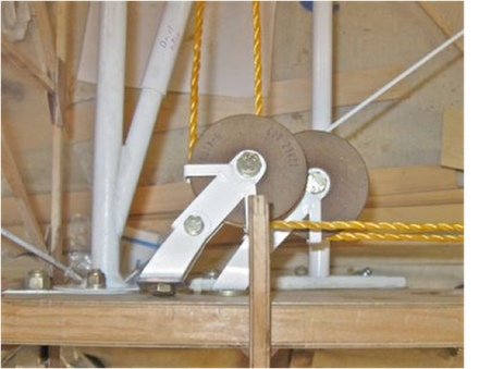
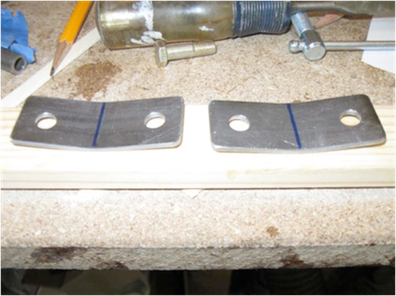 This is the bracket I made to angle the upper pulley on the front spar. I used .090 4130 to make sure the cable tension would not deflect the bracket.
 Another angle of the cable runs and pulleys.
 This angle is from the rear spar.
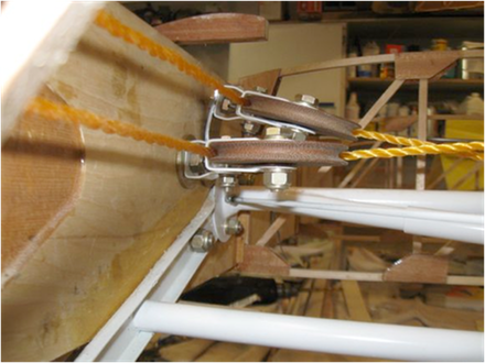
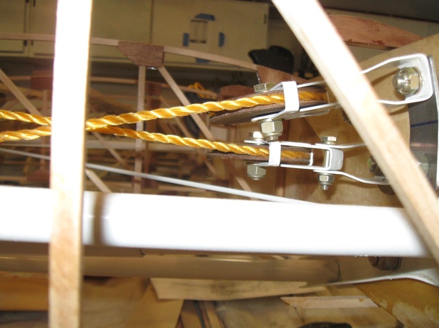
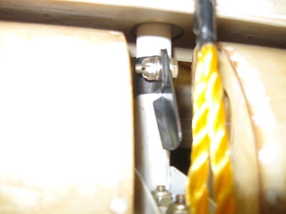
 This picture is a view from the top of the front spar looking down.
Side view from inside the wing next to the “N” compression strut.
 This shot shows the rear pulley over the rear spar; the cable clears the spar through the full range of the aileron.
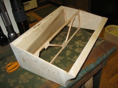
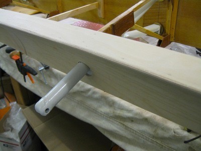
The next step was to make the aileron stop bracket. I first made a stock aileron stop but that didn’t work with the aileron horn that I made for the wood aileron. I decided to make one that was easily removed with two AN3 bolts and flat brackets rather than the 1/2″ tubes as shown in the plans. The new design worked out well to establish the 17 degrees of travel up and down for the aileron.
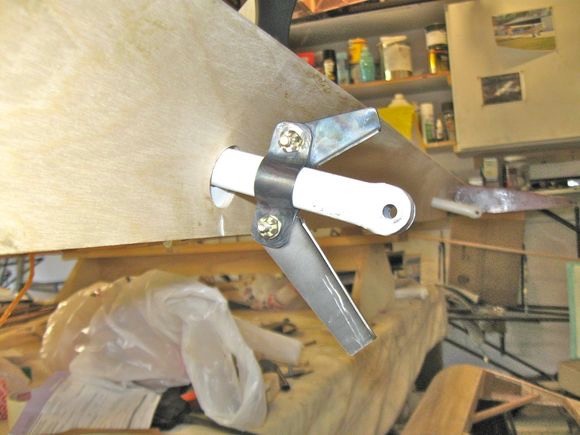 Finished aileron stop without the aileron installed.
 View from the underside with the aileron installed and the lower stop ground to match aileron horn.
 Top side view of the stop with the aileron installed.
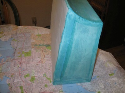
The next logical step on my wing was the false spar/aileron cove. I first test fitted a piece of metal cove and realized it would not fit well so I decided to make a wood cove by laminating two pieces of 1/16″ ply to match the end profile of the ribs. I made a jig using particleboard to laminate the cove. Laminating was very easy using epoxy resin to bond the surfaces together. When removed from the jig there was no spring back and the cove fit perfectly. I was concerned about how the cove would react under the pressure of the covering material so I made a test box representing the wing aft of the rear spar between two ribs. My first covering showed a lot of bowing on the cove so I removed the cover and added a top edge of 1/16″ ply to the cove and re-covered the test box. The results were much better. I still had some scalloping of the edge so I decided to make reinforcements for the cove similar to the ones used by Piper. I used the Piper drawing to fabricate a similar part out of wood and installed after the cove was glued in place. I followed that with a edge blocking for the final top ply edge. The cove came out very nice. I still have to add the bottom edge but will wait until the wing is flipped over when working on the fuel tank bay.
 This is a picture of the trial fit of the metal false spar/cove. Not a very good fit at all.
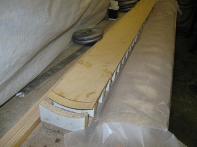
Here is the lower half of the jig for fabrication of the coves. Note the offset ends to glue to the next section. This step was surprisingly easy.
 The top and bottom of the jig match the end profile of the ribs. Two pieces of 1/16" ply are clamped inside with epoxy. The ends are off set so they can glue up to the next piece.

This shows how the offset ends of each cove piece fit together.
 Here is a test fit of the finished cove.
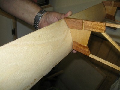 Another view to show the fit.
 This is the test box I used to see how the cove reacted under pressure from covering without any top edge. It did not turn out well with out the top edge.
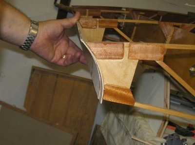
 I decided to make a wood reinforcement
as per the Piper drawings to help with distortion of the cove. I
installed the pieces between each rib bay. The "rib" going length wise in the test box is simply there so I can practice rib stiching latter.
I decided to make a wood reinforcement
as per the Piper drawings to help with distortion of the cove. I
installed the pieces between each rib bay. The "rib" going length wise in the test box is simply there so I can practice rib stiching latter.
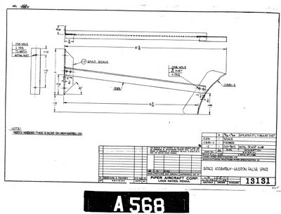
 The brace is identical to the Piper brace but made from wood.
Lastly I glued on a blocking edge of spruce along the top edge of the cove followed by the 1/16″ top ply edge. All in all I am very pleased with the outcome of the cove. I tested the wood cove against the metal to compare weight and the wood was lighter by about 20%. Cost for the wood cove for both wings was about $40 compared to about $300 for metal.
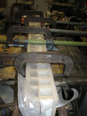
 Gluing and clamping cove.
The finished cove. I will be adding a strip of .020 aluminum inder the ply along the top and bottom so PK screws can be used to attach the flap and aileron gap seal latter after covering.
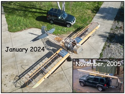
This brings me up to date on my wings. The next step will be to build up the second wing to this same point. The second wing is currently hanging from the ceiling. I will need to build the second flap and aileron (parts all ready to assemble) and to install the hangers and other hardware. This should go pretty quickly as all the parts are made but more importantly I don’t have any R&D to do on the second wing. My next new step will be to fabricate the fuel tank and mounting hardware so I can then cover the leading edge of the wing with ply to finish out the wings. Getting closer every day!
Return to Past Posts and Pictures by Date